Artiglio
Excellence in componentsLanguage: English
 |
 |
 |
 |
 |

 Printable version
  Request informations
  Tell a friend…
| Path of insertion
Path of insertionA fundamental step for the right placing of attachments with vertical guide is to establish the path of the insertion that is the direction in which a dental prosthesis is placed upon or removed from the supporting tissues or abutment teeth.
It is usually up to the operator the choice of the path of insertion through a general evaluation of the involved elements made by a parallel analyser inserted in a parallelometer (see Fig. 1 and 2).
The result is therefore a middle course between the mesio-distal and the bucco-lingual walls of the dies but it is compromised by subjective considerations and a not always coherent visual analysis.
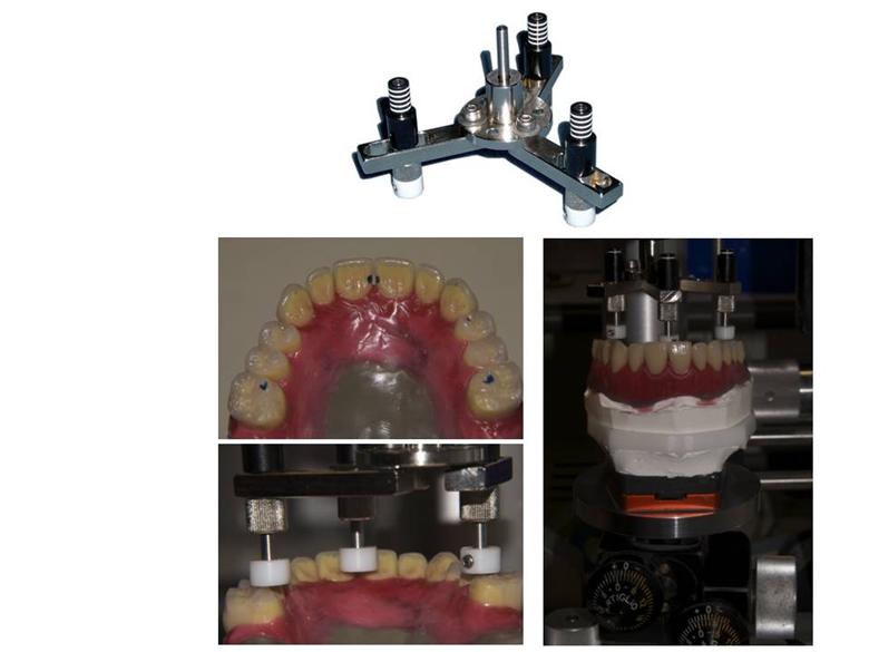
We think that the evaluation of this fundamental parameter deserves a more analytical procedure that starts from the precise measurement of the occlusal plane. To obtain this right value it is essential to use a specific tool named S25/R (surveying blade) that must be mounted in a parallelometer.
To find out the occlusal plane the movable arms of the S25/R must be brought to contact to the following points:
UPPER MODEL
Anterior side: the more occlusal point (usually the palatal area of incisors or the cingulum area of canines)
Posterior side: palatal cusps of first molar
LOWER MODEL
Anterior side: incisal edge of incisors
Posterior side: vestibular centric cusps of first molar
and the base must be inclined till the number of lines showed in all movable arms is the same (see Fig.3).
From this “value”, to make easier the insertion and the removal of the prosthesis, it is suitable to tilt of about 5° the axis of the occlusal plane, procedure allowed by RAP model holder base (see Fig. 4), equivalent to about 5 mm between the anterior quota and the back quota of the model, anteriorly lifting the upper models and posteriorly lifting the lower models.
This tilt corresponds to around 3 lines of the movable arms of S25/R, if RAP base is not in the laboratory.
|


